¶ Products covered
Products likely to be referred to on this exam include but are not limited to:
- PowerEdge MX Platform Server Components
- OpenManage Enterprise Modular (OME-E)
- PowerEdge MX Platform Networking Components
- iDRAC9 and Life cycle Controller
¶ Exam Topics
Topics likely to be covered on this exam include:
MX-Series Features (27%)
- Describe MX7000 hardware chassis components and numberingschemes
- Compare MX740c/MX750c/MX760c compute sleds and features
- Describe the 1U versus 2U sleds
- Describe MX5016s storage sleds and configurations
- Describe the features of 16G (DDR5, E3 storage, PERC, BOSS-N1, and CAC/PIV)
- Describe network switches and/or I/O fabric
- Describe the ATMOS components
MX7000 Administration (29%)
- Identify the MX Chassis Management Architecture and define the multichassis management groups
- Describe key features of OME-M that support management of the MX7000 chassis
- Configure storage sled management, mapping drives, and drive/enclosure assigned configuration
- Compare the internal storage versus using Fabric C with external storage
- Describe use of slot profiles, creating logs, and the iDRAC Service Module
- Describe how to perform firmware updates with the catalog
- Use key features of iDRAC specific to MX Modular (e.g., resetting iDRAC)
- Describe the main features of Lifecycle Controller
MX7000 Installation (17%)
- Describe the infrastructure and out-of-the-box setup on an MX7000
- Describe the power-on options
- Employ the Chassis Deployment Wizard to configure the initial chassis.
- Deploy server templates
MX7000 Implementation (19%)
- Identify hardware requirements of the various MX7000 network configurations (e.g., network cards, switches)
- Implement the Fabric Expander Module with the in-chassis network switch
- Understand the relationship between the Fabrics in Chassis Management Groups and Chassis backup lead
- Describe the initial switch set-up requirements
- Understand the SmartFabric Architecture
- Describe the VLAN Scale and L2 multicast Operation
MX7000 Troubleshooting (8%)
- Understand MX7000 troubleshooting (e.g., Minimum to POST and alerts)
- Understand the MX7000 troubleshooting logs
- Describe the Left Control Panel LCD PIN Management and/or Right Control Panel Field Replacement Auto-configuration
¶ MX7000 Chassis
- Eight storage/compute sled slots at front
- Support for 2 and 4 socket sleds
- Support for 16 drive 12 Gb/s SAS storage selds
- Rear IO options including 25GbE Ethernet, 100GbE Ethernet, 12Gb/s SAS and 32Gbps fibre channel (with future speeds being supported through upgraded IOMs
- Three I/O networking fabric
- No midplane on fabrics A and B,
- Fabrics and and B mezz cards connect directly with the IOMs
- Up to two chassis management modules
- Up to 6 hot pluggable, redundant 3000 W power supplies
- Three cooling zones exist to provide cooling on demand for front and rear components and PSUs
¶ Compute
¶ MX740c
- Dual socket, single-width
- Up to two Intel(r) Xeon(r) scalable processors with up to 28 cores per processor
- Up to 24 DIMMs of fast DDR4
- Onboard storage, up to six 2.5" SAS/SATA or NVMe drives
- Up to eight per chassis
¶ MX840c
- Dual or Quad socket, double-width
- Two or four Intel(r) Xeon(r) scalable processors with up to 28 cores per processor
- Up to 48 DIMMs of DDR4
- Up to four per chassis
- Onboard storage, up to eight 2.5" SAS/SATA or NVMe drives
¶ MX750c
- Uses Intel Whitley platform
- Supports third generation Intel Xeon (Ice Lake) processors
- Intel Optane Persistent Memory 200 Series (Barlow Pass) are supported
- Up to six SAS/ATA or NVMe drives are supported
- Other supported components
- Dell MX SAS or NVMe PERC or HBA
- MX Jumbo PERC or HBA Jumbo PERC
- Mezz cards
- BOSS
- IDSDM
- TPM
- PCIe Gen4
- Up to 32 DDR4 DIMMs (LR and RDIMM)
- Max capacity of 2 TB (LRDIMM) or 8 TB (RDIMM)
¶ MX760c
- Supports fourth generation Intel Xeon (Sapphire Rapids) processors
- 32 DDR5 DIMMs (RDIMM), max 8TB up to 4800 MT/s
- 4 x 2.5" or 6 x 2.5" NVMe/SAS/SATA or 8x E3.s NVMe PCIe Gen 5 SSD drives
- Added support for PERC12 RAID controller
¶ Storage
¶ MX5016s
- Individual or shared drives can be mapped with multiple compute sleds. Needs appropriate PERC or HBA options. Cluster aware OS needed when mapping to shared drives
- Both the 2 and 4 socket servers share drives with the MX5016s using the dedicated MX5000s SAS switch in Fabric C (only). Internal server drives may be combined with up to seven storage sleds in one chassis. Mix and match storage and compute nodes within the eight available slots depending on workload requirements
- HA features such as hot-pluggable drives and hot serviceable extenders help prevent downtime.
- Front access, means that the MX5016s is always accessible to swap or add drives as needed
¶ Fabric
- Multi chassis, scalable fabric
- Open automation. Gives customer choice of hardware, platforms, operating systems and management services.
The MX-series networking switches are as follows:
- MX9116n Fabric Switching Engine (FSE). 16 x 25 GbE server facing ports, 2 x 100 GbE uplink ports, 2 x 100GbE/32G FC uplink ports and 12 x 200 GbE Fabric Expander ports
- MX7116n Fabric Expansion Module (FEM). 16 x 25 GbE server facing ports and 2 x 200 GbE Fabric Engine ports
- MX8116n Fabric Expansion Module (FEM). 8 x 100GbE or 16 x 25 GbE server facing ports and 2 x 400 GbE Fabric Switching Engine ports
- MX5108n Ethernet switch. 8 x 25 GbE server facing ports, 2 x 100 GbE uplink ports, 1 x 40 GbE port and 4 x 10GBase-T ports
- MXG610s Fibre Channel Switch. 16 x 32 Gbps FC internal ports, 8 x 32 Gbps FC SFP+ ports and 2 x 32 Gbps QSFP+ operating at 32 Gbps or 16 Gbps speeds
¶ Chassis
The MX7000 chassis has two major assemblies
- The Chassis Tub (Front).
This provides the structure for mounting PSUs, sleds and the front fans - Chassis Tub (Rear).
This houses the central bulkhead structure and mounting for the main chassis board, AC connections and rear-end modules.
Broadly speaking, the front view of the chassis can be split in to three components.
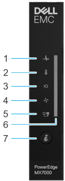
- Left Control Panel which comes in three flavours:
- LED Only
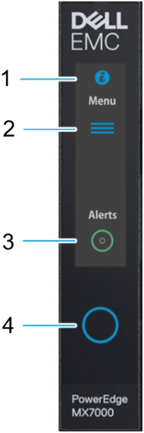
- LCD Only
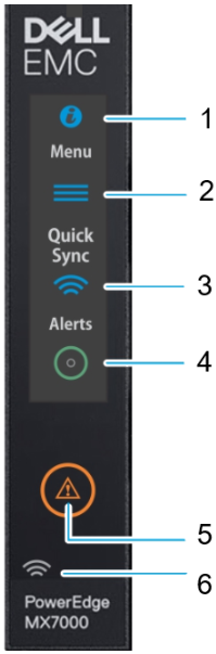
- LCD and QuickSync Module
the QuickSync is only available on the LCD version
-
The LCD panel allows 'at-the-box' management to be carried out. This panel will display status messages and the initial IP address
-
The LCD touch panel is not hot swap and requires that the enclosure be powered down before replacement.
¶ Front
¶ Left Panel
¶ LED
|
|
¶ LCD (no QuickSync)
|
|
¶ LCD with QuickSync
The QuickSync option allows the user to connect OpenManage Mobile to the enclosure
|
|
¶ ID Button and Wireless Button Status
| Status | ID Button (top) | Wireless Button (Bottom) |
|---|---|---|
| Healthy | Blue | Off |
| Fault | Blink Amber | Off |
| System ID | Blink Blue | Off |
| Healthy, Wireless ON | Blue | White |
| Fault, Wireless ON | Blink Amber | White |
| System ID, Wireless ON | Blink blue | White |
| Healthy, Wireless Communication | Blue | Blink white |
| Fault, Wireless Fault | Blink amber | Blink amber |
| System ID, Wireless Fault | Blink blue | Blink amber |
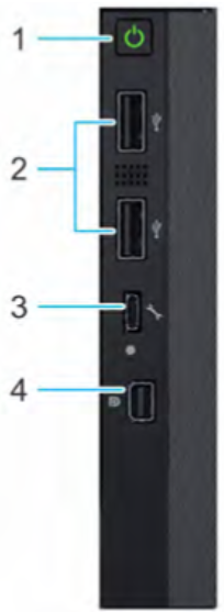
¶ Right Control Panel
Right control panel has the following features:
- Information tag
- Connects to the interposer board/main distribution board
- Contains a CMOS battery. This is to save the backup of the chassis config in the event of a power loss
- Micro-AB direct management port. This works in the same way as the iDRAC direct port on Dell servers
- Internal ROM used by the MMs to store chassis-level configuration parameters.
It should also be noted that the left control panel connects to the right control panel which then connects to the main distribution board.
|
|
The information tag has the following information on it:
- MAC Address and secure password
- Express service code
- Quick Resource Locator (QRL)
¶ Centre
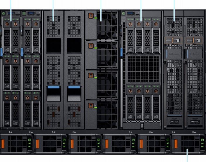
|
|
The MX7000 chassis supports three types of sleds
- Max of eight single width sleds
- Max of four double width sleds
- Max of seven single width storage sleds
- Combinations of the above
¶ Compute sled numbering
For single width sled (MX740c, MX750c and MX760c), the numbering is (left to right) 1,2,3,4, four fans, 5, 6, 7 and 8
For double width sleds (currently only MX840c), the numbering is (left to right) 1, 3, 5, and 7.
¶ Fans
In the centre of the chassis, you will find cooling fans.
- Maximum 100W fan
- They are numbered 1 through 4, top to bottom
- MM manages the Smart Fan Controller (SFC) configuration and operability modes through the i2C interface using IPMB-like (Intelligent Platform Management Bus) protocol. In the event of a communication failure, the SFC will manage the fans based on the MM-offline parameters.
- 3+1 redundancy, hot swap
- For cooling IOMs, MMs
¶ PSU
Along the bottom of the chassis, you will find up to 6 PSUs.
- Supports up to six 3000W platinum class
- Accessed from the front
- Grid redundancy, uses two data centre grids, connecting in such a way that a total grid loss can be survived.
- Both 220 and 110 volt AC are supported in the chassis. These can be mixed. If there are an equal number of high and low-line PSUs, the high-line PSUs should be enabled.
- PSUs are numbered 1 through 6, left to right (front)
- Each PSU has two fans. If there is a fan failure, the whole PSU must be replaced.
PSU power connectors on the rear of the chassis are numbered 6 to 1, left to right)
The PSUs also indicate overall health and if they are connected via AC or DC power.
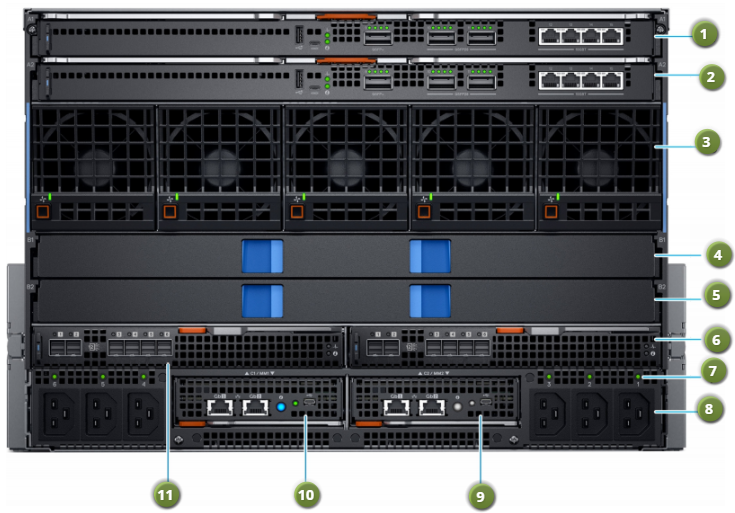
¶ Rear
|
|
¶ Network Fabric (fabric A and B)
- Internal connection of the main IO subsystem in the MX7000 is referred to as fabric A and fabric B.
- These two fabrics are directly connected to the sleds
- Fabrics A and B have two IOMs (A1, A2, B1, and B2) for redundancy. Each IOM connects to all eight compute nodes.
- MX9116n, MX7116n and MX5108n IOMs support 25G speeds on server facing ports.
¶ Storage Fabric (fabric C)
- Intended for storage applications
- Intended to support up to 24 Gb/sec SAS or Fibre Channel at 32 Gb/sec
¶ Rear fans
- 5 80mm fans
- Cool compute and storage sleds
- Hot swap, 4+1 redundant
¶ Power sockets
- Power supplies are accessed from the front, AC connectors on the rear
- Six C22 inlets. Three left, three right.
- "AC good" indicator next to each socket
- C22 inlet connectors allow for higher exhaust temperatures.
- C20 to C21 jumper cord is requried to connect to PDU
- PSU numbered 6 to 1, left to right.
¶ Management Module (MM)
- Control the overall chassis power, cooling and physical user interfaces (i.e. front panel)
- Up to two hot swap MM, minimum of one
- Each module has the following:
- Two RJ45
- One micro USB-B
- One System ID button which blinks ID LED on the front of the chassis. Also serves as chassis health status LED indicator (blue for good health or blinking amber if unhealthy)
¶ Internal
The main PDB handles power distribution, low-speed signaling, connecting to other boards, cables and fabric C. All the components in the following image are contained in the rear rub assembly
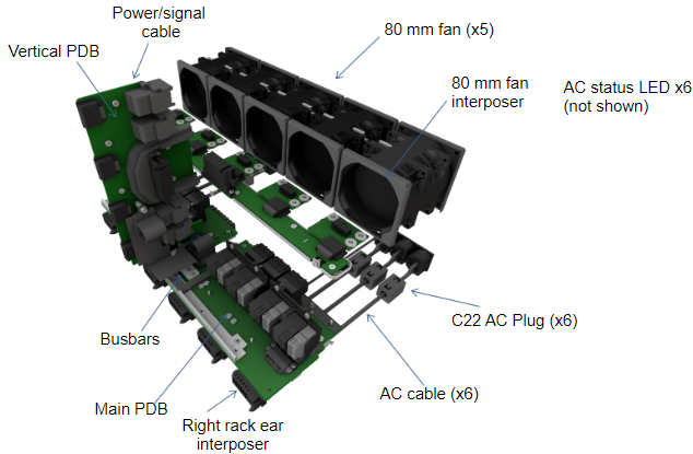
There are two main infrastructure boards:
¶ Main Distribution board
- Sits horizontally near the floor of the chassis
- No active components, but many signals are carried through this board
- Connecting to the board from the front
- Six PSUs
- Eight compute sleds connect for power, management signals and other fabric connections
- Connecting to the board from the rear
- Management modules to connect overall chassis management and control
- Two fabric C IOMs
Main distribution board is not a servicable part and is part of the rear tub assembly
¶ Vertical power board
- Sits above the main distribution board
- Cable connects power distribution board to the rear fan board
- No active components, but many signals are carried through this board
- Connects to Main distribution board with a flex cable, power and ground bus bars
- The four front fans connect to vertical power distribution board
- Fabric A and B modules connect at the rear for power, management signals and other fabric connections
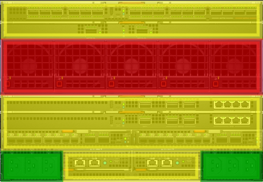
¶ Cooling
¶ Front Airflow
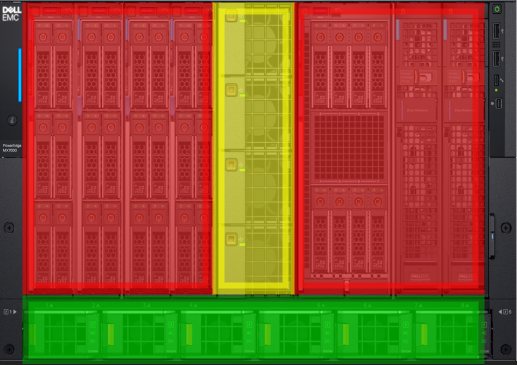
- Red area Cooling is provided by the rear 80mm fans. Cools the sleds only
- Yellow area The 60mm fans provide cooling for the rear IOMs (A, B, and C) as well as the MMs
- Green Area Dedicated airflow for the PSUs
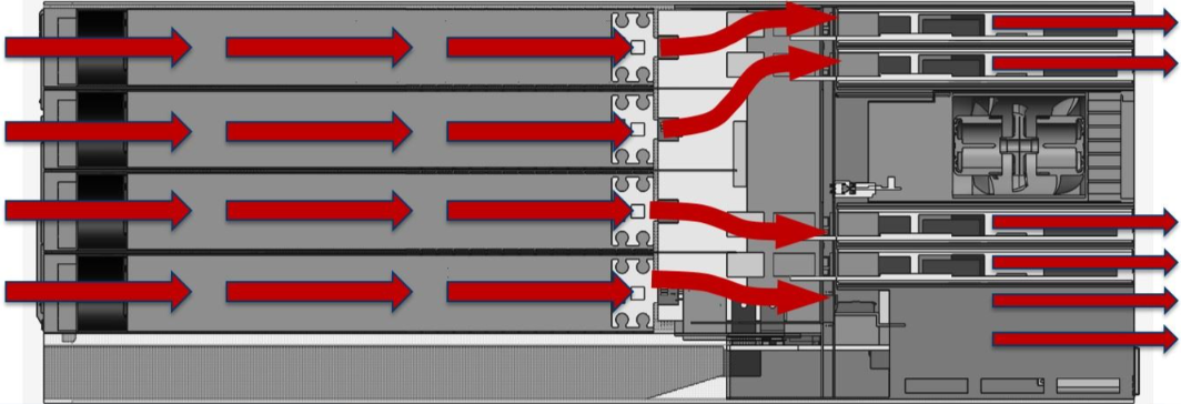
¶ Rear Airflow
- Red area 80mm fans. Cools the sleds only
- Yellow area The front 60mm fans provide cooling for the IOMs (A, B, and C) as well as the MMs
- Green Area Dedicated airflow for the PSUs
¶ Sleds and PSUs

- Sled cooling is controlled by the rear fans
- PSU cooling controlled by the fans built in to the PSUs
- Image above shows the path of the air through the chassis for sleds and PSUs
- Separate paths for exhausts
¶ MMs and IOMs
Front four fans provide cooling to fabrics A, B, and C as well as the Management Modules.
¶ At-the-box Management
MX-series architecture has removed the need for separate compute, storage and network management consoles. In the MX you will find end-to-end life cycle management of all components with the embedded OpenManage Enterprise - Modular (OME-M) console.
Through OME-M and the onboard management capabilities, the chassis can be managed whilst standing in front of the chassis or remotely with the web interface.